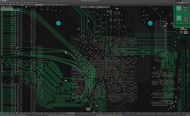
You may click Reports to open the Board Report dialog in which you can specify the content to be included when generating a detailed report for the board.
Board information - displays the horizontal and vertical board dimensions of the board itself, along with information for each listed category such as the total number of the listed item. Axis Snap Range - when the cursor is axially-aligned and within this distance from an enabled object snap point (and the Axes feature is enabled), a dynamic guide line will display to indicate that alignment has been achieved. Snap Distance - when the cursor is within this distance from an enabled object snap point (and snapping is enabled for the active layer), the cursor will snap to that point. Object for snapping - object snap points (hotspots) that will be snapped to during an edit action, such as placement or movement. Snapping - used to control whether object snapping is Off, if object snapping only occurs to the enabled objects on the Current Layer, or if object snapping occurs to the enabled objects on All Layers. A dynamic alignment guide line is displayed when alignment is achieved, from the current cursor location to the axially-aligned object snap point (hotspot). The Axis Snap Range defines the distance within which X or Y axial-alignment will occur. Axes - used to toggle whether the cursor will axially-align (in either the X or Y direction) to the enabled Objects for snapping. A Snap Guide will override the Snap Grid. Guides - used to toggle whether the cursor will snap to manually placed linear or point Snap Guides. The active snap grid is displayed on the Status bar, and in the PCB editor Heads Up display ( Shift+H to toggle on/off). When this option is enabled the cursor will pull, or snap, to the nearest snap grid location.  Grids - used to toggle whether the cursor will snap to the active workspace grid. Snap Options - providing options to determine cursor snapping (first image):. Object buttons – toggle each object button to enable/disable the ability to select that object type. All Objects button – select remove object filtering so that all types of objects may be selected. Selection filter - The options in this section of the panel determine which PCB objects may be selected in the workspace. The following sections of the panel are used to configure: The images below show the sections of the panel that are used to configure the unified cursor-snap system.Īccess controls for the Unified Cursor-Snap System in the Properties panel, including the Snap Options, Grid Manager and Guide Manager. The Unified Cursor-Snap System is configured in the Properties panel (accessed when there are no design objects currently selected in the design workspace). These features combine to ensure streamlined placement and alignment of objects in the PCB workspace. Axis Snapping - a feature to pull the cursor, in either the X or Y direction, so that it axially-aligns with an object's hotspot. Object Snapping - enabling placed objects to pull the cursor into position, based on cursor proximity to that object's snap points (hotspots). Snap Guides - that can be freely placed and provide a handy visual cue for object alignment. User-Definable Grids - available in both Cartesian and Polar formats. The system brings together different sub-systems to collectively drive the way that the cursor snaps onto given sets of preferred coordinates: Variable geometry boards - where component pins are often placed on different metric and imperial grids - serve to add greater complexity to this objective. The objective is for the system to be able to place the logical cursor onto sensible and useful coordinates without the user needing to specify these in a high-resolution way. 'Cursor-snap' is the process whereby the physical mouse cursor's pixel position on the screen drives the position of a 'logical cursor' in the coordinate space of a design document such as a PCB. Together, these features are referred to as the Unified Cursor-Snap System.
 #ALTIUM DESIGNER PCB PLACE LOGO SOFTWARE#
Snap grids can also be restricted to Components or Non-Components.Īs well as the snap grid, the software includes a number of additional snap features, designed to help you accurately position and align design objects.

Snap grids are prioritized, with the highest priority grid available at the current location, being applied automatically.

Multiple snap grids can be defined, and these can be restricted to a specified area if required. The PCB Editor is a grid-based design environment - design objects are placed on what is referred to as the placement, or snap grid.


 0 kommentar(er)
